Liquid-Solid Co-Printing of Multi-Material 3D Fluidic Devices via Material Jetting
B. Hayes, T. Hainsworth, and R. MacCurdy. “Liquid–Solid Co-Printing of Multi-Material 3D Fluidic Devices via Material Jetting.” Additive Manufacturing, vol. 55, 2022, p. 102785., https://doi.org/10.1016/j.addma.2022.102785. </a>
Summary
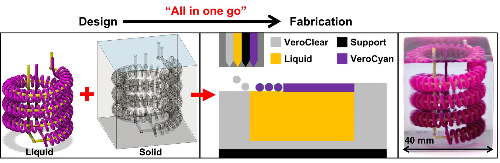
Multi-material material jetting additive manufacturing processes deposit micro-scale droplets of different model and support materials to build three-dimensional (3D) parts layer by layer. Recent efforts have demonstrated that liquids can act as support materials, which can be easily purged from micro/milli-channels, and as working fluids, which permanently remain in a structure, yet the lack of a detailed understanding of the print process and mechanism has limited widespread applications of liquid printing. In this study, an “all in one go” multi-material print process in which non photo-curable and photo-curable liquid droplets are simultaneous deposited, is extensively characterized. We envision the liquid–solid co-printing process as a key new capability in additive manufacturing to enable simple and rapid fabrication of 3D, integrated print-in-place multi-material fluidic circuits and hydraulic structures with applications including micro/mesofluidic circuits, electrochemical transistors, lab-on-a-chip devices with in-situ reagent deposition, and robotics.
Main Learnings
-
Select the head voltage to underjet liquid in order to better contain liquid by the solid matrix; 19 V is a recommended setting for Stratasys Polyjet systems but users should characterize their system similar to figure 6 to verify.
-
When overjetting, the roller drags liquid into the solid matrix resulting in liquid fingers that are on the size order of 300 μm for a circular channel of radius 500 μm. Channels printed parallel to the printhead direction of motion can reduce the effect of liquid fingers
-
Full capping layer encapsulation of a liquid surface occurs at N ≥ 5 print layers (135 μm)
-
If the cured photo-resin droplet density is less dense than that of the non photo-curable liquid, then the cured droplet can be freely supported by the liquid as the buoyancy force alone can support the cured droplet
-
If the cured photo-resin droplet density is more dense than that of the non photo-curable liquid, then the cured droplet may be supported by the non photo-curable liquid’s surface tension. However, surface deformations due to roller and droplet impacts create a variable surface tension force that can cause a droplet to sink. The best practice is to use attachment points to the solid matrix when possible in this situation
- The minimum repeatable channel cross-section (W x H) is 250 x 108 μm2 without regard for part placement orientation
- The minimum repeatable channel cross-section is 250 x 81 μm2 when the channel is oriented parallel to the printhead direction of motion
- Printed microfluidic channel cross-sectional areas are less than 60% that of the design channel cross-sectional areas due to the liquid finger phenomenon.
Mechanism:
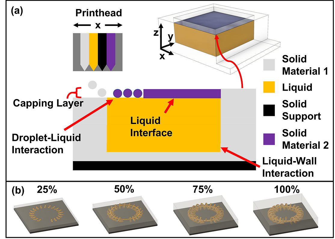
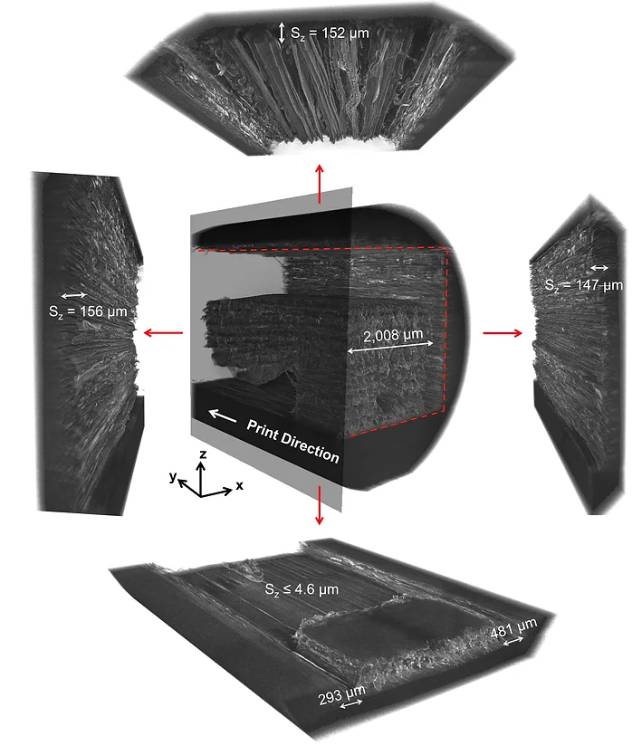
This work demonstrates that liquids can be used as a support material for subsequent photo-polymer droplets. The lower left figure describes this process in detail. Once the liquid has been deposited, the next print layer, denoted as the capping layer, involves photo-polymer droplets impacting a liquid surface. In the use of any combination of working fluid and photo-resins, there are four potential governing force balance cases: (1) the photo-resin is less dense than the non-solidifying liquid and surface tension is significant, (2) the photo-resin is less dense than the non-solidifying liquid and surface tension is negligible, (3) the photo-resin is more dense than the non-solidifying liquid and surface tension is significant, and (4) the photo-resin is more dense than the non-solidifying liquid and the surface tension force is negligible. Scenarios 1 and 2 are desirable as they enable the fabrication of free floating structures; however, due to Stratasys photo-resin material properties, Polyjet liquid-solid co-printing falls within scenario 3. This technique can be used to make fully hermetic micro/mesofluidic channels as shown by the XRD imaging in the lower right figure.
(left) High speed imaging of VeroCyan droplet impact on cleaning fluid; (right) OpenFOAM model of droplet train impact
Sample Micro/Mesofluidic Devices Possible:
The ability to simultaneously deposit non photo-curing (liquid) and photo-curing (solid) materials enables rapid fabrication of planar, 3D, and multi-material fluidic devices. Listed below are examples of such devices. We note the ease in which this technique allows fabrication of micro/mesofluidic devices. 3D printing enables those with no prior soft lithography and micro-fabrication experience to produce micro/mesofluidic devices thus making the field more accessible.
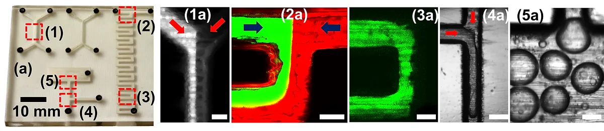
Planar Micro/Mesofluidics
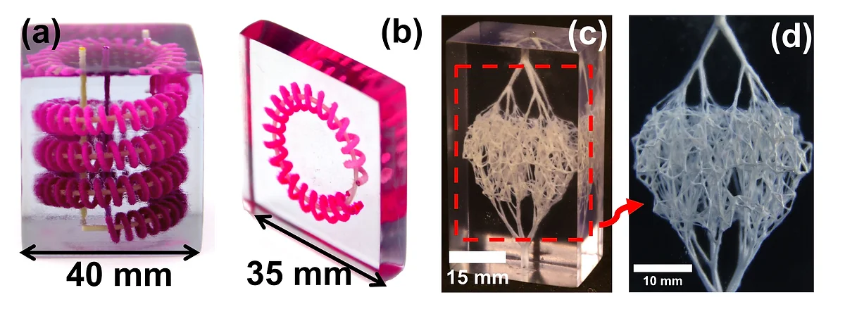
3D Micro/Mesofluidics
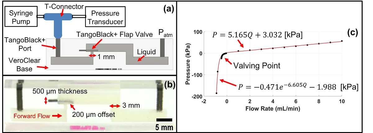
3Multi-Material Flap Valve