OpenVCAD
Programmable geometry and spatial material properties for multi-material fabrication
OpenVCAD is a Python library for designing objects whose geometry and material properties change from point to point, and for compiling those designs into files that printers and simulation tools can use. It is developed in the Matter Assembly Computation Lab at the University of Colorado Boulder.

Designing with OpenVCAD
An OpenVCAD object has two parts. Its geometry is an implicit shape, a signed distance field that is negative inside the object, zero on its surface, and positive outside. Shapes are combined with Boolean operations and transforms, or imported from meshes, CAD models, and scans. Its attributes are named fields attached to that geometry, such as color, stiffness, Shore hardness, temperature, or the mix of printing materials. An attribute can depend on position (x, y, z) and on d, the distance to the surface, so it can change along an axis, around a center, or inward from the surface.
Designs are ordinary Python. This part is a cube intersected with a sphere, with three cylinders removed:
import pyvcad as pv
import pyvcad_rendering as viz

cylinder = pv.Cylinder(pv.Vec3(0, 0, 0), 2.0, 9.0)

root = pv.Difference(
    pv.Intersection(
        pv.RectPrism(pv.Vec3(0, 0, 0), pv.Vec3(8, 8, 8)),
        pv.Sphere(pv.Vec3(0, 0, 0), 5.5),
    ),
    pv.Union(
        cylinder,
        pv.Union(
            pv.Rotate(90, 0, 0, cylinder),
            pv.Rotate(0, 90, 0, cylinder),
        ),
    ),
)

viz.Render(root)
Attributes make a design multi-material. Here two printing materials blend from the bottom of a cylinder to its top:
import pyvcad as pv
import pyvcad_rendering as viz

materials = pv.default_materials

# A cylinder 12 mm wide and 20 mm tall, from z = -10 to z = 10
root = pv.Cylinder(pv.Vec3(0, 0, 0), 6.0, 20.0)

# Blend two materials from the bottom to the top
top = "(z + 10) / 20"
fractions = pv.VolumeFractionsAttribute([
    (f"1 - {top}", materials.id("cyan")),
    (top, materials.id("magenta")),
])
root.set_attribute(
    pv.DefaultAttributes.VOLUME_FRACTIONS, fractions
)

viz.Render(root, materials)
Nothing is turned into voxels or toolpaths while you design. When a design is ready, a compiler samples its fields for a particular process. Translation models can convert design intent into what a machine needs, for example a target hardness into material fractions for an inkjet printer or into nozzle temperatures for foaming filament. Because the design stores properties rather than printer settings, the same source can be compiled for more than one process. The Getting Started guide and the Functional Grading Guide cover these ideas step by step.
Supported outputs
| Process | Output | OpenVCAD component |
|---|---|---|
| Multi-material inkjet (material jetting) | Image stack assigning a material to every voxel | Material inkjet compiler |
| Full-color inkjet | Image stack in cyan, magenta, yellow, black, white, and clear | Color inkjet compiler |
| Vat photopolymerization (LCD, DLP, masked SLA) | Grayscale exposure mask for each layer | Vat photo compiler |
| Multi-material vat printing | Synchronized grayscale image stacks for two- or four-vat systems | Multi-material vat compiler |
| Filament printing through a slicer | PrusaSlicer or OrcaSlicer .3mf project with per-region settings, process states, or color and material mixing |
Slicer project compilers |
| Filament printing, direct | G-code with gradient-aware toolpaths for mixing extruders, tool changers, and foaming filaments | VCAD-Slicer (separate repository) |
| Finite element simulation | Meshes with material properties: .xdmf with .h5, or Abaqus .inp
|
Simulation compiler |
3D-printed pre-surgical planning models
Medical scans record a value at every point inside the body. OpenVCAD reads these volumes directly and maps each value to a printable property, so internal structure carries through the whole print instead of being reduced to a few surface meshes. The models in this section are research prints and have not been clinically validated.

One scan, two models
A single CT scan of a pair of feet can be translated in different ways. For a visual model, radiodensity becomes color, so bone and soft tissue look different. For a mechanical model, radiodensity becomes target stiffness and toughness, which OpenVCAD converts into mixtures of soft and rigid printing materials. The bones in that print are rigid, while the skin and heel stay soft.


CT phantoms
A phantom is a printed object that is meant to be scanned. For this separate print, radiodensity from a foot CT scan was mapped to mixtures of a radiopaque resin (RadioMatrix), which blocks more X-rays, and a conventional black resin (VeroBlack). The printed phantom was then CT-scanned. The comparison is visual; it is not a quantitative validation of the phantom.

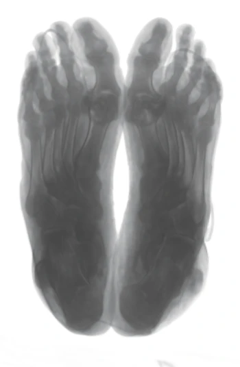 Original CT scan
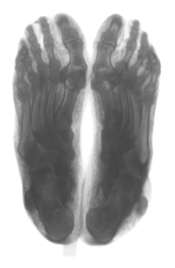 CT scan of printed phantom
More in the volume data guide and on the lab's pre-surgical planning research page.
Metamaterials and lattice design in Python
Lattices and other architected materials are built from repeating unit cells. In OpenVCAD a lattice is ordinary Python: choose a cell, lay the cells out in a region or across a surface, and set properties for the whole structure, for each cell, or for each strut. The lattice tools are included in the OpenVCAD package and are free to use under its noncommercial license.




Scroll each row sideways, or open the full catalogue.
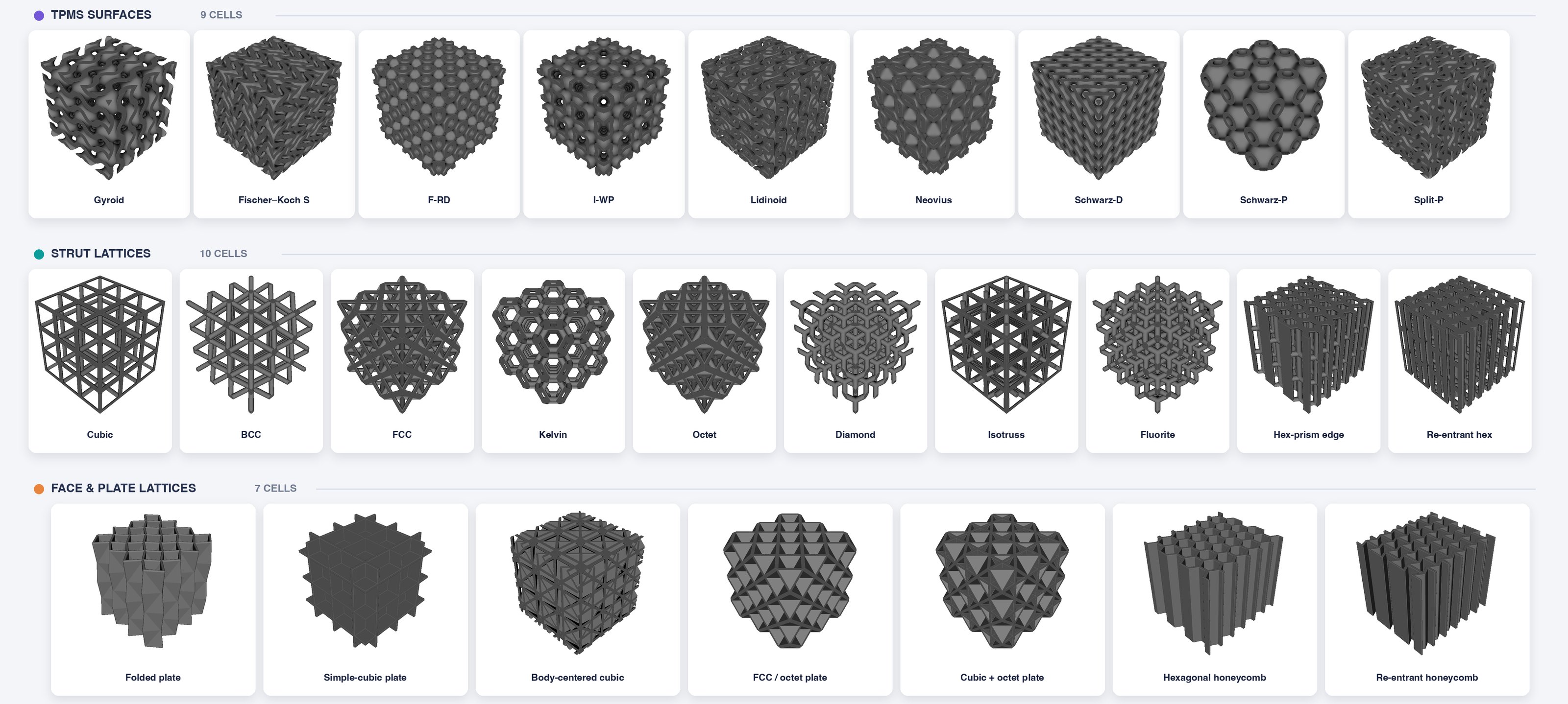
A gyroid lattice filling a 30 mm cube (units are millimeters), three cells on each side:
import pyvcad as pv
import pyvcad_metamaterials as mm
import pyvcad_rendering as viz

cell_map = mm.rectangular_cell_map(
    (pv.Vec3(-15, -15, -15), pv.Vec3(15, 15, 15)),
    cells=(3, 3, 3),
)
root = mm.gyroid(cell_map, wall_thickness=1.6)

viz.Render(root)
Replacing mm.gyroid with another cell, such as mm.schwarz_p, changes the lattice.

Grading material inside each cell
Properties can follow the cell pattern instead of the overall shape. In this workflow a hardness field is defined on one unit cell, softer toward the strut tips and harder at the center, then repeated through the lattice and printed. Because the field belongs to the cells, it moves with them when a lattice is mapped onto a curved shape.


The same idea on a BCC lattice. With coordinates="cell", x, y, and z run from 0 to 1 across each unit cell, so one expression repeats in every cell. Here hardness is highest at each cell's center:
import pyvcad as pv
import pyvcad_metamaterials as mm
import pyvcad_rendering as viz

cell_map = mm.rectangular_cell_map(
    (pv.Vec3(-15, -15, -15), pv.Vec3(15, 15, 15)),
    cells=(3, 3, 3),
)
root = mm.bcc(cell_map, beam_radius=0.9, node_radius=1.2)

# 0 at each cell's center, 1 at its corners
r = "sqrt((x-0.5)^2 + (y-0.5)^2 + (z-0.5)^2) / 0.866"
hardness = pv.FloatAttribute(f"85 - 50 * {r}")

shore = pv.DefaultAttributes.SHORE_HARDNESS
root.set_attribute(shore, hardness, coordinates="cell")

viz.Render(root)
Lattices that follow a surface
Cells do not have to sit on a rectangular grid. A conformal map lays them out over a curved surface, so the lattice follows the shape of the part.

Geometry and material grading together
Both kinds of grading can be combined. In this gyroid wing, the cells shrink toward the tip to keep detail in the thinner sections, while two materials blend along its length.


Guides: metamaterials and conformal lattices.
Functionally graded toolpaths and slicer settings
On filament (FFF) printers, much of a part's behavior comes from how it is printed: the blend of filaments in the nozzle, nozzle temperature and flow, infill density, and surface texture. OpenVCAD treats these process parameters and slicer settings as spatial fields, just like color or hardness, and compiles them into files that filament printers and slicers already use.
Gradient-aware toolpaths
Some parameters cannot change instantly. A mixing extruder needs time to flush one blend before the next, and foaming filament responds to a temperature change with a delay. The gradient-aware slicer cuts each layer's toolpaths along contours of the design field and orders them so the printer follows the gradient instead of jumping across it, then writes G-code directly from the OpenVCAD design.


Slicer settings as fields
Mainstream slicers already handle toolpath planning, supports, and printer profiles. The slicer-project compiler keeps that work in the slicer: it divides each field into regions, exports a matching sub-mesh for each one, and writes a PrusaSlicer or OrcaSlicer project in which every region carries its own settings. Settings that shape toolpaths, such as infill density or fuzzy skin, are applied per region; machine states, such as nozzle temperature and flow, change when the printer crosses a region boundary.


From the example 02_infill_density_bar.py.
Texture and process state together
In this bunny, both Shore hardness and surface texture (fuzzy skin) are defined as fields. OpenVCAD converts hardness into nozzle temperature and flow rate for a foaming TPU filament, then writes a PrusaSlicer project whose regions carry the matching temperature, flow, and fuzzy-skin settings. In the print, lighter areas are softer and darker areas are harder.

foaming_fuzzy_bunny.py.
One hardness design, two printing processes
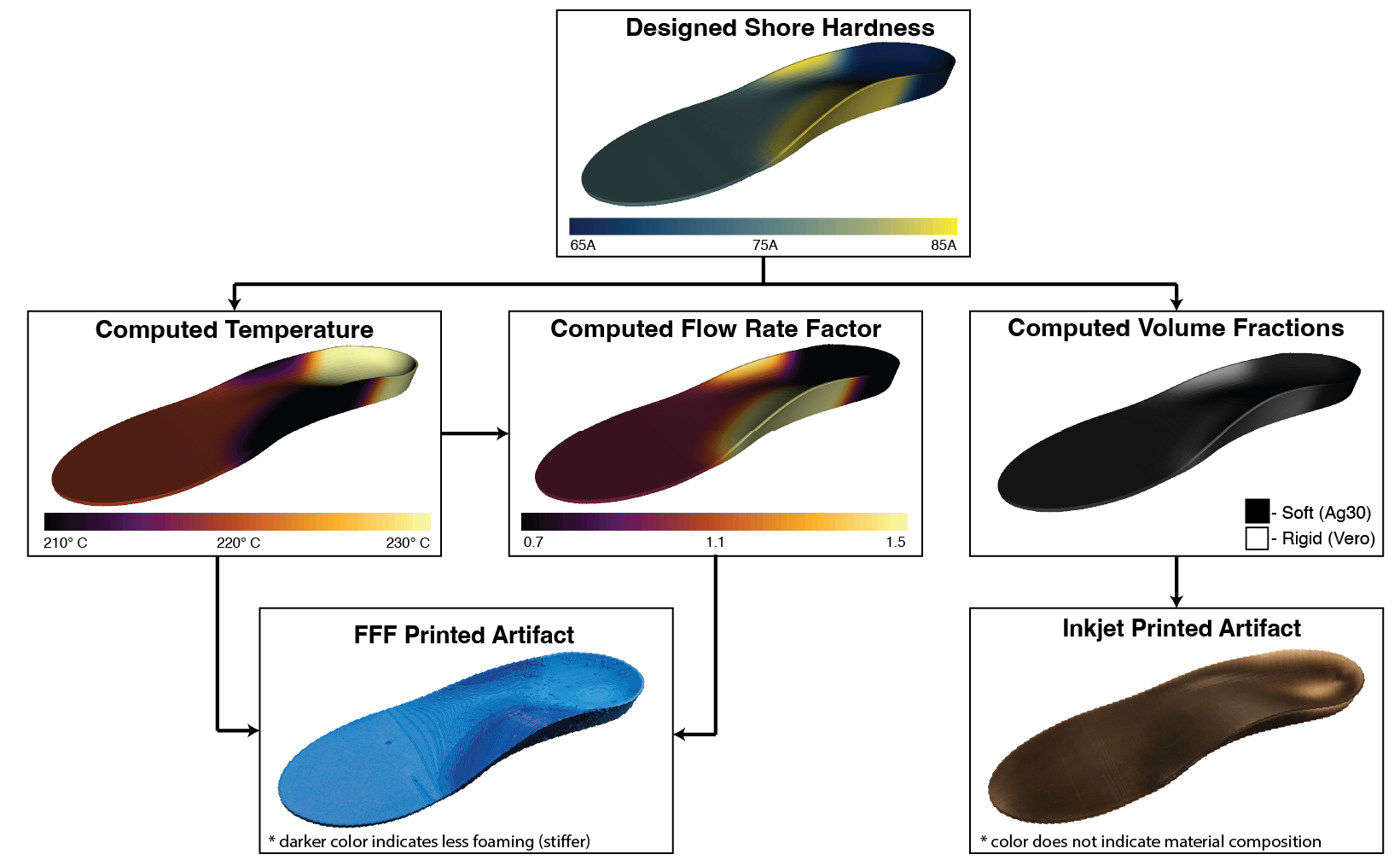
The same kind of hardness field can also be compiled for an entirely different process. This insole design asks for a soft 65A heel, firmer 85A arch and side support, and 75A elsewhere. From that one field, OpenVCAD computes nozzle temperature and flow rate for foaming TPU on a filament printer, and soft and rigid material fractions for an inkjet printer.


In the filament print, darker blue means less foaming and a stiffer region; the inkjet print's color does not show material composition. Full figure with the computed fields. Guides: slicer projects and attribute translation.
Simulation-driven design
OpenVCAD exports designs as finite element meshes that carry their material properties, and it reads solver results back in. An imported result, such as displacement or strain energy, becomes one more attribute on the original design. It can then decide where stiff material goes, how thick lattice struts are, or which print settings a region receives, not only what shape the part takes.


The import step: with the solver's node positions (points), tetrahedra (cells), and per-node result (energy) loaded as arrays, the result is attached to the original design like any other field:
results = pv.UnstructuredFieldDataset.from_tetrahedra(points, cells)
results.add_point_scalar("strain_energy", energy)

# The result becomes an ordinary attribute on the original design
strain_energy = results.float_attribute("strain_energy")
part.set_attribute("strain_energy", strain_energy)

# ...and can drive material, geometry, or process fields
stiff = strain_energy.normalize(0.2, 1.2).clamp(0.0, 1.0)
Guides: simulation-driven design and the simulation compiler.
Volume printing
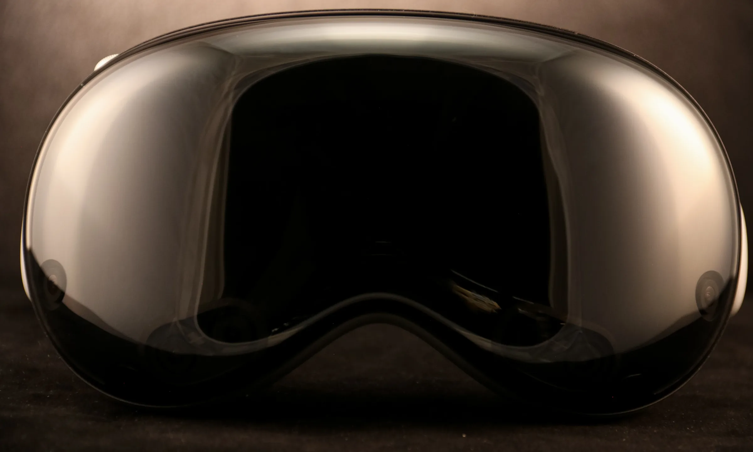
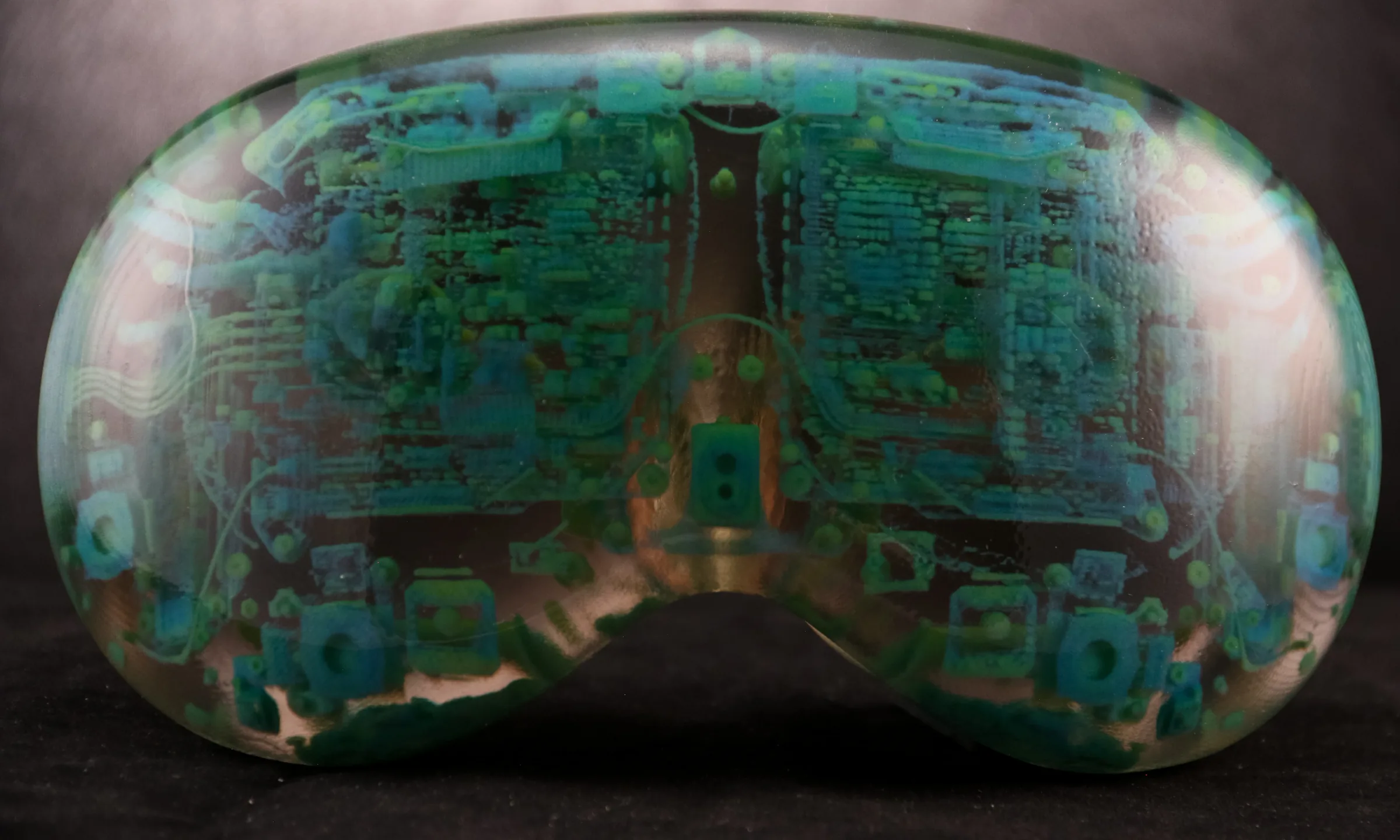
Here, volume printing means printing sampled 3D data, such as a CT scan or a simulation, so that color and transparency vary through the whole object and not only on its surface. OpenVCAD maps each data value to a color and an opacity and compiles the result for a full-color inkjet printer.
 Original device
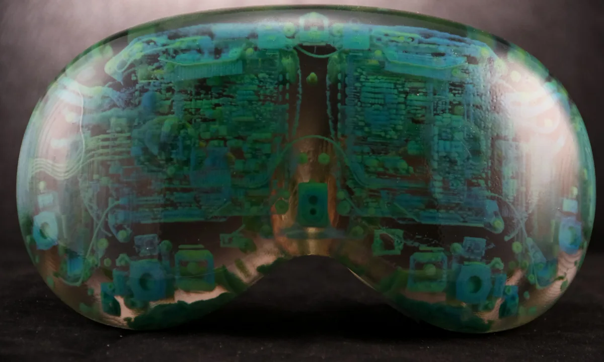 3D print of CT data
Fire simulation
A fire simulation stores temperature and smoke density at each point. In this example, temperature sets the color and density sets the opacity.

Fire data: the fire.vdb example dataset from the OpenVDB project. More in the volume data guide.
Inspecting designs
The OpenVCAD Renderer opens from Python with viz.Render(root). It shows the design tree next to the model, colors the model by any of its attributes, and includes tools to clip through it, probe values, and plot values along a line, so a design can be checked before it is compiled. Below, it shows the graded lattice from the metamaterials section, colored by hardness.

More examples


Publications
If you use OpenVCAD in your work, we ask that you cite the relevant papers below. BibTeX for each entry is on the publications page.
-
PreprintFunctionally Grading the Slicing Process by Compiling Design Intent into Slicer Projects
Compiles volumetric designs into ready-to-slice PrusaSlicer and OrcaSlicer projects, so spatial fields control slicer settings, printer state, and color or material mixing.
PDFarXivCitation -
PreprintDesign-Intent Compilation for Heterogeneous Fabrication
Describes designs as typed spatial attributes and translates them into material, process, or slicer outputs for material jetting and material extrusion without rewriting the design for each printer.
PDFarXivCitation -
Implicit Modeling for 3D-printed Multi-material Computational Object Design via Python
Introduces the Python API, multi-material lattice design, and links to finite element analysis for simulation-informed designs.
PDFarXivCitation -
Implicit Toolpath Generation for Functionally Graded Additive Manufacturing via Gradient-Aware Slicing
Generates filament-printer toolpaths directly from OpenVCAD's material gradients, allowing continuous changes in mixture, nozzle temperature, and other print parameters.
PDFDOICitationCode -
OpenVCAD: An open source volumetric multi-material geometry compiler
The original OpenVCAD paper: implicit geometry and material distributions compiled for multi-material inkjet printing.
PDFDOICitation
Using OpenVCAD
Install
OpenVCAD is installed from PyPI into a Python virtual environment:
python -m pip install OpenVCADSee the installation guide for supported platforms and setup.
Learn and explore
License
OpenVCAD is free for noncommercial academic and personal research under the University of Colorado's license. Commercial use requires a separate license.
Contact
For questions, collaborations, or commercial licensing, contact Charles Wade at charles.wade@colorado.edu.