Physical surface relief#
Physical surface relief turns a grayscale image or a Python-defined pattern into raised, printable geometry on a selected part of a model. You choose where the pattern goes, what controls its height, and how tall it should be. OpenVCAD creates a real relief volume that can be rendered, meshed, voxelized, simulated, and exported with the rest of the part.
This is different from a visual bump map: the outside shape of the part actually changes. All dimensions in this guide are in millimetres.
What you need#
Every relief design has four inputs:
Input |
What you provide |
|---|---|
Base solid |
The CAD model or closed triangle mesh that will receive the texture |
Selected surface |
One |
Height pattern |
A grayscale PNG or a |
Relief settings |
Maximum height, embed depth, and optional edge falloff |
The complete workflow is short:
# 1. Select one surface from the base model.
surface = ...

# 2. Define the height pattern.
height = pv.ImageHeightField(
    "pattern.png",
    amplitude_mm=1.0,
)

# 3. Turn that pattern into physical relief.
relief = pv.SurfaceReliefVolume(
    surface,
    height,
    embed_mm=0.3,
    edge_falloff_mm=1.0,
)

# 4. Optionally join the relief to the original part.
root = pv.BBoxUnion([solid, relief])
relief is already a geometry node. You can render or export it by itself when you only want the
added surface feature:
root = relief
viz.Render(root)
Unioning is optional; it simply attaches that relief volume to the original part.
embed_mm extends the relief slightly into the base part so the two volumes overlap and become
one printable solid. edge_falloff_mm is optional: it lowers the relief smoothly near the selected
surface boundary instead of ending at full height.
Select the surface to decorate#
CAD and triangle meshes use the same relief workflow, but you select their surfaces differently.
Select a CAD face#
Load the CAD model once, choose a face from it, and convert that same model into the base solid:
model = pv.CADModel.from_step("examples/data/3d_models/bracket.step")
face = model.face(20)
solid = model.to_node(use_fast_mode=True)
model.face(index) is useful when the input file is fixed and you know the face index. You can
also find faces by geometric properties:
upward_faces = model.select_faces(
    normal=pv.Vec3(0, 0, 1),
    min_dot=0.95,
)
face = max(upward_faces, key=lambda candidate: candidate.area)
Available filters include face index, surface type, normal direction, area range, and
bounding-box overlap. For CAD authored in Python, first convert the CadQuery body with
pv.CADModel.from_cadquery(...), then use the same face() or select_faces() methods.
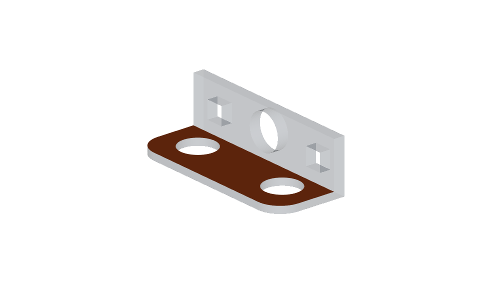
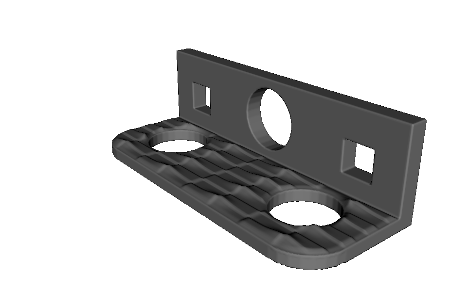
The complete bracket example is
examples/geometry/surface_relief/cad_face_png_relief.py.
Select triangles from a mesh#
For a closed triangle mesh, pass the IDs of the triangles that make up the surface patch:
source_mesh = pv.SurfaceMesh("examples/data/3d_models/domed_tile.stl")
triangle_ids = list(range(450))

patch = pv.TriangleMeshSurface.from_selection(
    source_mesh,
    triangle_ids,
    u_axis_hint=pv.Vec3(1, 0, 0),
)
solid = pv.Mesh(source_mesh, override_voxel_size=0.2)
The selected triangles must form one connected, open patch. Triangle IDs can come from a mesh editor, a stored face group, or a Python selection rule. The triangle-mesh conformal mapping guide shows how to select a region by triangle direction and connected component.
u_axis_hint is optional. Use it when the left-to-right direction of the pattern matters. Triangle
IDs follow the source file’s triangle order, so update a stored selection if the mesh is
retriangulated.
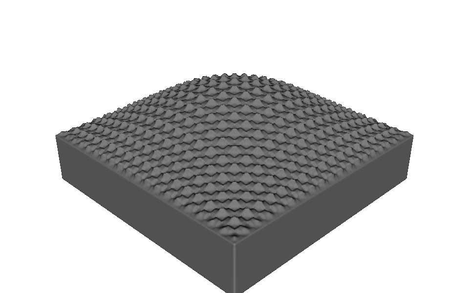
You can also create a TriangleMeshSurface from an already-open patch file or directly from
vertices and indexed triangles. See
examples/geometry/surface_relief/selected_mesh_png_relief.py
for the complete imported-mesh example.
Choose the height pattern#
The height pattern supplies values from 0 to 1 across the selected surface. OpenVCAD multiplies
those values by amplitude_mm, so 0 stays on the original surface and 1 reaches the maximum
relief height.
Use a PNG#
ImageHeightField loads a grayscale or RGB PNG:
height = pv.ImageHeightField(
    "examples/data/height_maps/dotted_checker.png",
    amplitude_mm=1.2,
    channel="luminance",
    mapping="repeat",
    repeats=(5, 5),
)
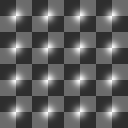
dotted_checker.png. Dark pixels stay low; light pixels rise toward amplitude_mm.The image controls are:
Setting |
Meaning |
|---|---|
|
PNG file to map onto the selected surface |
|
Height of a white pixel; black is 0 mm |
|
|
|
Place one copy across the whole selected surface |
|
Tile the image using the integer |
Image (u, v) = (0, 0) maps from the lower-left corner. If a pattern appears rotated relative to
the intended part direction, adjust the mesh u_axis_hint or rotate the source image.
Use fit for a logo, label, or one full-surface texture. Use repeat when a small pattern should
tile across a larger region. On a periodic CAD surface such as a cylinder, fit wraps one image
around the full surface; use an image whose left and right edges match when you want an invisible
seam.
Use a function#
FunctionalHeightField creates the pattern directly from normalized surface coordinates. In the
expression, x is the surface’s left-to-right coordinate and y is its bottom-to-top coordinate:
waves = pv.FunctionalHeightField(
    pv.FloatAttribute(
        "0.5 + 0.25*sin(10*pi*x) + 0.25*sin(8*pi*y)"
    ),
    amplitude_mm=1.4,
)
The function result is limited to the range 0 to 1, then scaled by amplitude_mm. This is useful
for waves, ribs, gradients, procedural textures, and other patterns that should remain editable
through a few parameters rather than an image file.
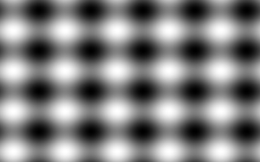
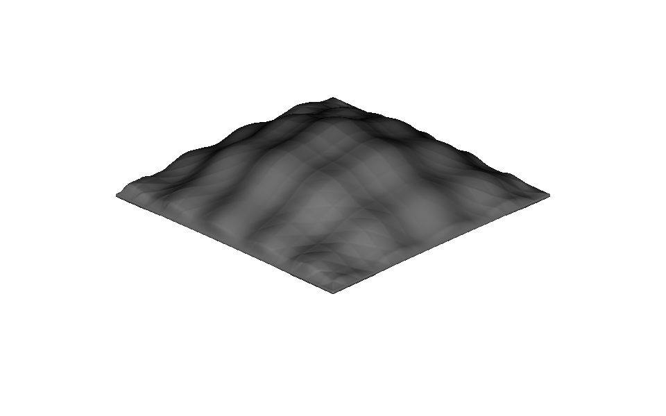
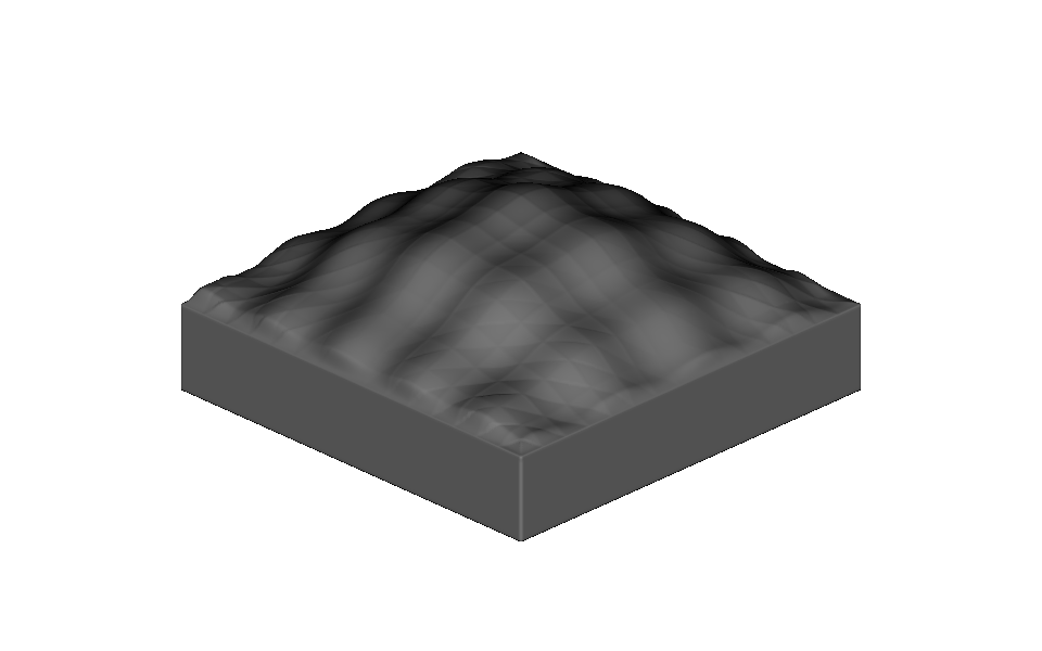
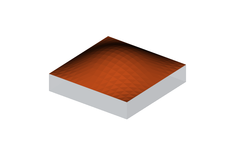
The middle image is the geometry created by SurfaceReliefVolume: the raised top, its selected
outline, and the thin embedded portion that can overlap another solid. The last image uses
pv.BBoxUnion([solid, relief]) to attach exactly that volume to the tile.
Run
examples/geometry/surface_relief/functional_wave_relief.py
to edit the expression and amplitude. It renders relief by itself; change root to
unioned_root to preview the attached part instead.
Wrap a continuous texture around a curved face#
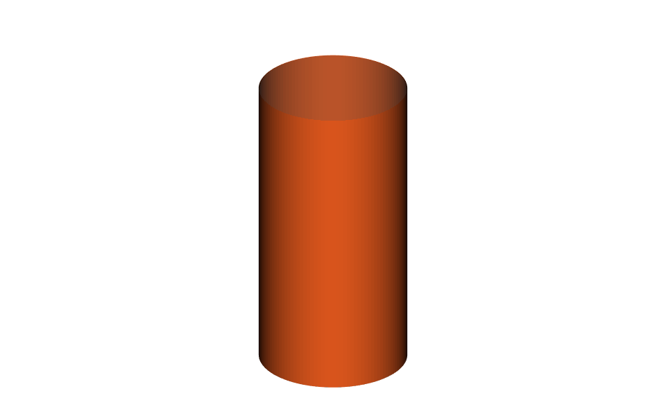
The cylindrical example combines the same ideas: CadQuery authors the base cylinder, a CAD surface-type filter selects its curved wall, and a fitted PNG supplies the height:
cylinder = cq.Workplane("XY").cylinder(40.0, 10.0)
model = pv.CADModel.from_cadquery(cylinder)
outer_wall = model.select_faces(surface_type="cylinder")[0]

skin_height = pv.ImageHeightField(
    "examples/data/height_maps/skin_microrelief.png",
    amplitude_mm=0.35,
    mapping="fit",
)
relief = pv.SurfaceReliefVolume(
    outer_wall,
    skin_height,
    embed_mm=0.20,
    edge_falloff_mm=0.8,
)
solid = model.to_node(use_fast_mode=True)
unioned_root = pv.BBoxUnion([solid, relief])

# Preview the wrapped relief shell without the base cylinder.
root = relief
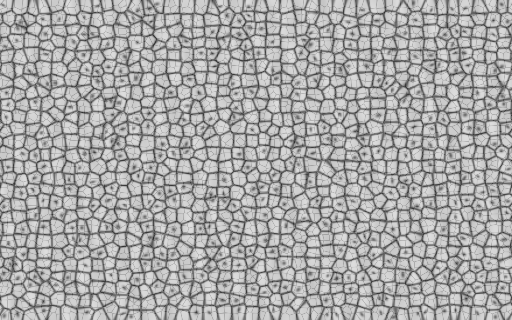
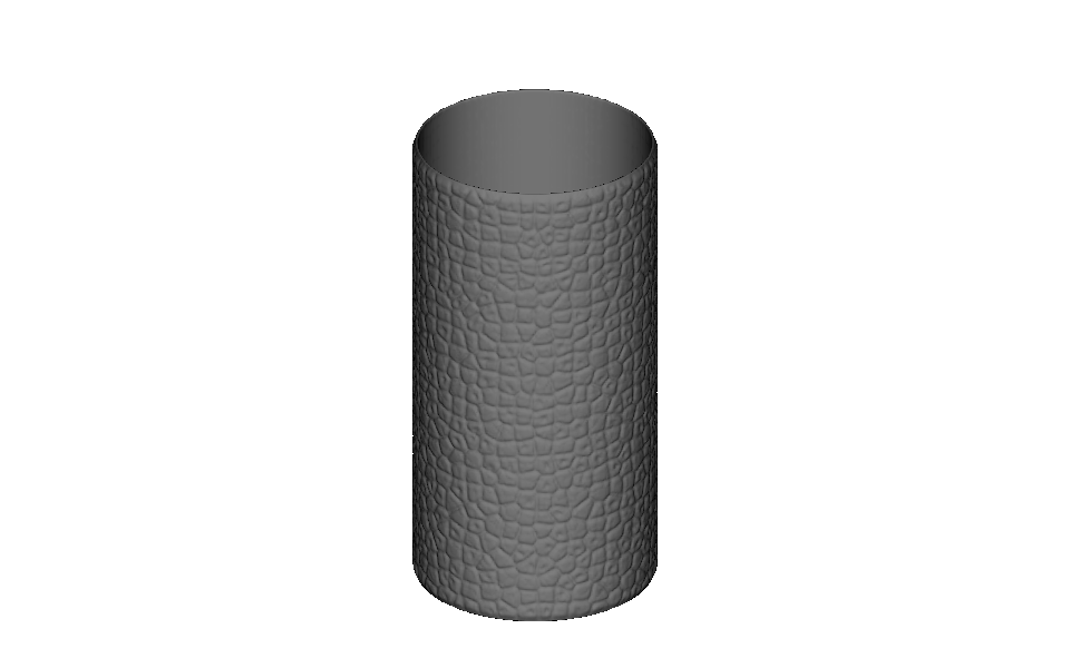
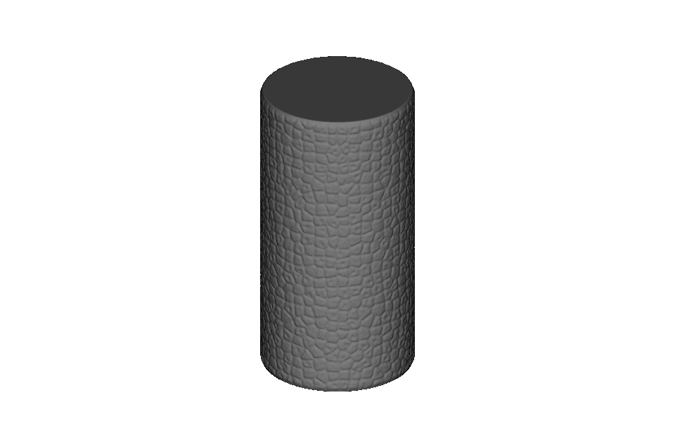
The packaged map is a synthetic, skin-inspired pattern with raised plateaus, furrows, and pore-like details. Its left and right edges match, so the texture closes around the cylinder. The 0.35 mm height is deliberately exaggerated so it is visible and printable; it is not patient-specific measured skin.
The standalone view shows the thin wrapped volume created from the selected wall. The unioned view
adds the original cylinder, including its top and bottom, beneath that same relief. The complete
cylindrical_skin_relief.py
example renders relief by itself; change root to unioned_root to preview the finished part.
Choose practical relief settings#
Control |
Good starting point |
|---|---|
|
Start with a height that is visible at the intended print scale, then reduce it if the texture is too strong |
|
Use a small positive overlap, often 0.2–0.5 mm depending on part and print resolution |
|
Use 0 to keep full height at the edge, or a positive distance for a smooth transition |
|
Use |
Sampling/export resolution |
Keep the voxel size small enough to resolve both the relief height and its narrowest feature |
As a starting point, use at least 4–6 voxels across the smallest pattern feature and several voxels through the relief height. A coarse preview or export can hide fine texture even though the relief definition is unchanged.
Surface relief currently creates raised geometry. It works on one selected CAD face or one connected open triangle-mesh patch at a time. Those simple boundaries make the authoring workflow predictable: select the region, choose the pattern, set the physical height, and join it to the part.